| Name | Designation | Email & phone | Photo |
|---|---|---|---|
| Head of the Research Group | |||
| Dr. Pijush Pal Roy Briefbiodata |
Outstanding Scientist & Head of the Rock Excavation Engineering | Eamil-Id : ppalroy@yahoo.com Phone : +91-326-2296032 (O) 0343-2546749 (O), 09431506000 (M) |
 |
| Rock Excavation Engineering | |||
| Dr. M. M. Singh Briefbiodata |
Chief Scientist | Eamil-Id : drmmsingh@cimfr.res.in / mms_cmri@yahoo.co.in Phone : +91-3262296028 Extn: 4293 (O), 947119233 (M) |
 |
| Dr. B. M. P. Pingua | Sr. Principal Scientist |  |
|
| Dr. C. Sawmliana Briefbiodata |
Principal Scientist | Eamil-Id : csla_cimfr@yahoo.com Phone : +91-3262296028 Extn: 4449 (O), 9471191134(M) |
 |
| Dr. M. P. Roy Briefbiodata |
Principal Scientist | Eamil-Id : mproy14@yahoo.com / mproycimfr@gmail.com Phone : +91-3262296028 Extn: 4455 (O), 9431315871 (M) |
 |
| Mr. R. S. Yadav Briefbiodata |
Sr. Technical Officer(1) | Eamil-Id : rsycfri@yahoo.co.in / rsyadav@cimfr.res.in Phone : +91-3262296028 (O), 9431318084 (M) |
 |
| Mr. R. K. Singh Briefbiodata |
Sr. Technical Officer(1) | Eamil-Id : rakesh1_12@yahoo.com Phone : +91-3262296028 Extn: 4449, 9431315626 (M) |
 |
| Mr. N. K. Bhagat Briefbiodata |
Sr. Tech. Officer (1) | Eamil-Id : narayan@cimfr.res.in Phone : +91-3262296028 Extn: 4447 (O), 9430394048(M) |
 |
| Mr. P. Hembram | Technical Assistant | |
|
| Mr. P. P. Mondal | Sr. Stenographer (Adm) | |
|
| Mr. Z. Ahmed | Sr. Technician (1) | |
|
| Mr. R. Sah | Lab. Assistant | |
|
| Mr. B. Mahato | Lab. Assistant | |
|
| Explosive and Explosion Laboratory | |||
| Dr. R. R. Singh | Sr. Principal Scientist & Head of the Explosive & Explosion Laboratory | |
|
| Mr. Gautam Kr. Nandi | Sr. Technician (1) | |
|
| Mr. Vivek Kr. Himanshu Briefbiodata |
Scientist |  |
|
| Mr. BanshiTuri | Lab. Assistant (2) | |
|
| Mr. S. C. Dasaundhi | T.S. Gr. (1) | |
|
| 18 Results |
| Sl. No. | A brief description of Facilities/ Equipment/Tools/software with photos |
|---|---|
No Facilities Found |
|
| Sl. No. | Name | Sponsor | Duration | Objective | Major output(if any) | |||||||||||||||||||||||||||||||||||||||||||||||||
|---|---|---|---|---|---|---|---|---|---|---|---|---|---|---|---|---|---|---|---|---|---|---|---|---|---|---|---|---|---|---|---|---|---|---|---|---|---|---|---|---|---|---|---|---|---|---|---|---|---|---|---|---|---|---|
| 1 | Standardization of dragline blast designs to control vibration within safe limit (In house project of CSIR-CIMFR Dhanbad) | CSIR-CIMFR Dhanbad | Altogether 32 blasts were conducted at Dragline benches of East and West section of Jayant Project and Nigahi Project of Northern Coalfields Limited (NCL).
Blast vibration were recorded at four to six locations. The main monitoring locations were Madhauli sub-station, houses of the Madhauli village, Jayant West sub-station, Ashok Leyland service centre, Temple near Ashok Leyland service centre, Bucyrus Office, CGM Office of Nigahi Project, Colonies of the head quarter, Morwa Guest House, NCL Head Quarter (PanjareBhavan), Allahabad Bank, BSNL Office and CETI Gate. The structures responses of few important structures/houses viz. houses of the Madhauli village, BSNL Office, PanjareBhavan and headquarter colony at Singarauli were monitored. The recorded natural frequencies of the houses were in the range of 3.5–8.75 Hz. The amplification of vibrations (Ratio of PPV at roof/wall and to that on the ground) was observed in the houses and was in the range of 1.27–4.45. The incoming blast vibration had frequency in the range of natural frequency of the houses and resonance occurred, the resultant amplitude of the vibration in the houses got amplified. The maximum amplification were recorded when incoming blast wave has dominant frequency very close to the natural frequency of the house. Table 1 represents the response of various structures due to the blast conducted at Jayant and Nigahi projects. Table1: Responses of structures to blast vibrations and their natural frequencies
Fast attenuation of vibration was recorded at shorter distances whereas at far-off distances the attenuation was slow and was influenced by low frequency blast wave characteristics. The persistence of vibration was up to 13 seconds at Singrauli Township, whereas at shorter distances it was only of 2-4.2 seconds. The recorded dominant frequencies of vibrations were more than 8 Hz up to 3250 m and were less than 8 Hz at far-off distances. The FFT analyses of vibration data revealed that the concentration of vibration energy were in the range of 3.3 to 17.4 Hz.
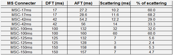
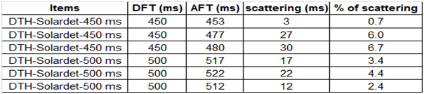
The delay interval between the holes in a rows and between rows were optimised and accordingly the blasts were experimented which gave excellent results in terms of fragmentation with reduced level of vibration. There were no back breaks in any of the blasts. The recommended delay timing between the rows are in the range of 7.8 ms/m–22.4 ms/m of effective burden of the Dragline blast conducted at Jaynat Project and 9.5 ms/m–23.1 ms/m of effective burden of the Dragline blast at Nigahi Project. The delay scattering test performed at Nigahi project for the MS connecters used at Dragline bench is presented in Table 2. The Table shows excessive scattering in the MS Connectors of 17 ms, 42 ms and 100 ms. Table 3 shows that the delay scattering in DTH of M/s Solar Industries India Limited at Nigahi project and was within limits. The optimised blast design sequence of the dragline bench blast of Jayant Project and Nigahi Projects are presented in Figure 1 and Figure 2 respectively. Table 2: Delay scattering test details performed at Nigahi Project, NCL
Table 3: Delay scattering test details performed at Jayant Project, NCL
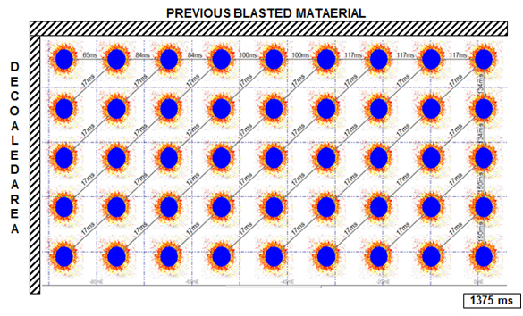
Fig.1: Recommended blast detonation sequence for dragline bench of Jayant Project
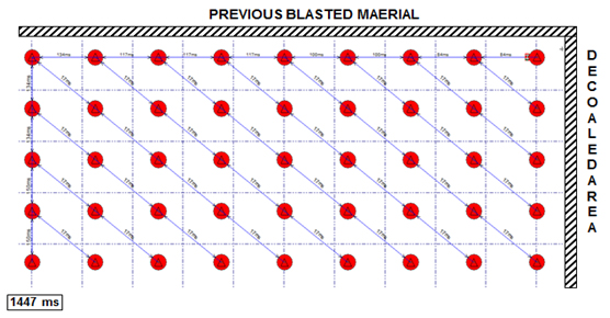
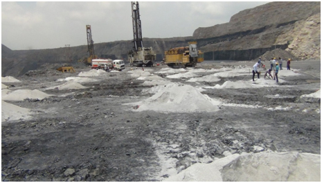
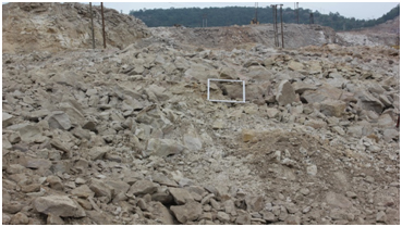
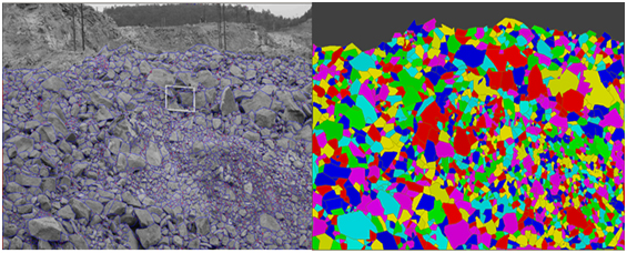
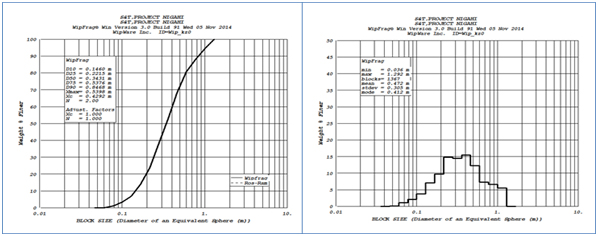
Fig. 2: Recommended blast detonation sequence for dragline bench of Nigahi Project The blasting face of East dragline bench of Nigahi Project is presented in Photograph 1. Fragmented view of the blasting face is depicted in Photograph 2. The fragmentation analyses of the blast were carried out. The outputs of the detailed analyses of the fragment size are depicted in Figures 3 & 4. The average mean size of the block is 0.472 m (diameter of an equivalent sphere) and the most common size of the block is 0.412 (diameter of an equivalent sphere) after excluding the fine size of the fragmented rock in the analyses. The maximum size of the boulder is of 1.292m (diameter of an equivalent sphere).
Plate-1: The views of the charging of blast holes at Dragline bench of East Section, Nigahi Project, Northern Coalfields Limited
Plate 2: The views of the fragmentation resulted from the blast conducted Dragline bench of East Section, Nigahi Project, NCL.
Fig. 3: Netting and contouring of block sizes of fragments resulted due to Dragline bench of East Section, Nigahi Project, NCL.
Fig. 4: Histogram and cumulative size curve view of fragmented block sizes Dragline bench of East Section, Nigahi Project, NCL. | |||||||||||||||||||||||||||||||||||||||||||||||||||
| 2 | Blast design and fragmentation control – key to productivity. S&T Project, Funded by Ministry Of Coal, Govt. of India | Ministry Of Coal, Govt. of India | Field investigations were carried out at Nigahi Project of NCL and SonepurBazari Project of ECL. Altogether, 38 experimental blasts were conducted at hard and medium hard OB benches being operated by Draglines and shovels. Out of 38 blasts, 19 blasts were conducted at Nigahi Project and also 19 blasts were performed at SonepurBazari project.
During the trial blast at Nigahi Project, average explosives in a blast holes varied from 55 kg to 900 kg in case of shovel bench blasting having hole depth of 9.5 m to 19 m whereas in case of dragline bench the hole depth were of 42 m deep and the average explosives loaded was 2810 kg. The burden × spacing in case of shovel benches were of 4 m × 6 m, 7 m × 8 m, 7 m × 9 m, 8 m × 8 m, 8 m × 9 m, 8.5 m × 9.5 m. 10 m × 10 m whereas in case of Dragline bench it was 10 m × 13 m. The designed powder factor for dragline and shovel benches were in the range of 1.66 to 2.53 m3/ kg.
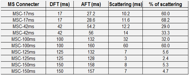
At SonpurBazari project, 19 trial blasts were conducted and the average explosives in a blast holes varied from 165 kg to 406 kg in case of shovel benches ( hole depth: 10 to 18.5 m) and 687 to 1450 kg for dragline bench having hole depth of 15 to 31 m. The burden × spacing for shovel benches were 4 m × 5 m, 4.5× 5.5 m, 5 m × 6 m, 5.5 m ×6.5 m, 6 m × 7 m and for dragline bench it was 8 m × 9 m and 9 m ×10 m. All experiments trials were conducted at hard to medium hard sandstone rock OB benches. Before conducting trial blasts, the quality test of boosters, explosives and blasting accessories (particularly MS connectors) were carried out. The delay scattering tests were performed at Nigahi project for MS connecters used at Dragline bench and are presented in Table 1. The table shows the excessive scattering in the MS connectors of 17 ms, 42 ms and 100 ms.
Table 1: Recorded delay detonators scattering test results at Nigahi Project, NCL
The blast design parameters data collected from 38 blasts from two experimental sites are analyzed to find out it’s impact on rock fragmentation level. The main important parameters which decide the fragmentation level of particular blasts are burden to hole diameter ratio, spacing to burden ratio, stemming column length, stiffness ratio, explosives amount and its type, initiation mode and charge/powder factor. The near field blast vibration signatures were also recorded to diagnose the impact of delay on blast fragmentation. The blast wave signature recorded at 100 m from one of the hard OB dragline bench blast is depicted in Figure 1. In this blast the delay interval between the holes in a row were 17 ms and between the rows the delay intervals were of 65 ms, 84 ms, 100 ms, 125 ms and 142 ms in subsequent rows. Figure 2 represents the blast wave signature recorded at 100 m from the hard OB bench (dragline bench) blast at SonepurBAzari project. In this blast the delay interval were kept 17 ms between the holes in a row and 65 ms and 84 ms between the rows.
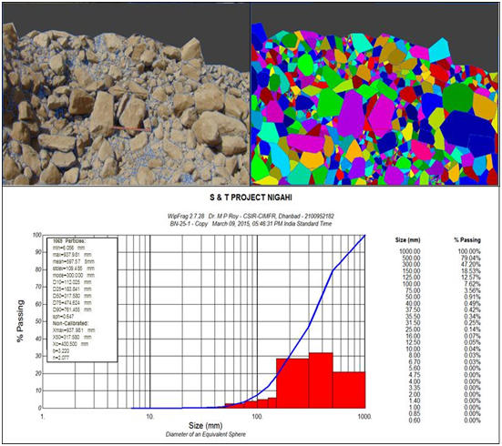
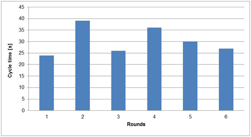
The fragmentations achieved from these blasts reflected different results. Most of the blasts results were excellent in terms of fragmented rock and its uniformity. Few blast results also have shown scattered results in terms of big size boulders and fine and dust particles as represented in terms of uniformity index (n). Most of the blasts resulted with good muck piles. The fragment size analyses were carried using Wipfrag software. One of the fragmented size analysis of the blast conducted at medium hard OB bench of Nigahi project is shown in Figure 3. Figure 4 represents the loading cycle of the 10 cubic meter shovel operated at hard OB shovel bench of SonepurBazari project.
Fig. 3: Netting, contouring, histogram and cumulative size curve view of fragmented block at medium hard OB bench of Nigahi project.
Fig.4: Plot of cycle time of shovel from the blast conducted at hard OB shovel benchof SonepurBazari Project. | |||||||||||||||||||||||||||||||||||||||||||||||||||
| 3 | Scientific studies for redesigning of induced blasting pattern to increase its effectiveness and to advise on ring hole blasting to minimize boulder formation at the proposed BG Panel BJ(1) in No. 3 Seam at GDK-11 Incline, RG-1 Area of SCCL, (CNP-3920/2014-15) | The objective of the study is to design induced blast design parameters for effective caving of overhanging roof in the BG Panel and optimization of the ring hole blasting for improved fragmentation and productivity at the mine.
Six ringhole blasts have been conducted in BG-J(2) of 3 Seam till now. Ring burden value of 1.5 m is used with the effective ring burden of 1.23 m for all ringhole blasting in coal. All the holes in the roof and sides of the gallery have been drilled with 55° inclination towards goaf. The total number of holes in full ring blasts varied from 30 to 35 and hole depth varied from 2.5 to 11.0 m. | Further project work is in progress. | |||||||||||||||||||||||||||||||||||||||||||||||||||
| 4 | Study and advice for optimization of blast design parameters usinf SME explosives at Malkera OCP, Bhelatand Amalgamated Colliery of M/s Tata Steel Limited (CNP-3925/2014-15) | M/s Tata Steel Limited | The main objective of the study is to evolve controlled blasting patterns using SME explosives in order to minimize ground vibration, noise/air overpressure and flyrock within the blasting zone of 100 to 300 m for the safety of nearby residential houses.
Twenty rounds of experimental blasts have been carried out till date with different drilling and charging patterns of holes using SME explosives. Twenty-four ground vibration data have been recorded at various locations in the Chaitudih Colony. Based on the distance of vibration monitoring points from the blast site, maximum charge per delay and total number of holes fired in the blasting round, the magnitude of ground vibration data recorded varied between 1.89 and 10.7 mm/s. | Further project work is in progress. | ||||||||||||||||||||||||||||||||||||||||||||||||||
| 5 | 3)Scientific study for enhancement of pull and coal yield per blast for solid blasting in coal at Degree-III gassiness underground coal mines of Parbatpur Colliery of M/s Electrosteel Castings Limited (CNP-3953/2014-15) | M/s Electrosteel Castings Limited | The main objective of the study is to increase the pull in solid blasting for enhancement of coal yield per blast in Degree-III gassiness underground coal mine of Parbatpur Colliery.
Till now, sixteen experimental blasts have been conducted in the development faces of No. 18 Top Seam in Block-II area with varying design patterns. Out of sixteen blasts, one blast is conducted using modified burn cut pattern and rest of the blasts are conducted with modified V-cut pattern. The average pull obtained with modified burn cut pattern of the blast is 0.75 m only, although a pull of 0.90 m is obtained in the cut area. The pull obtained, before dressing, with modified V-cut pattern using 1.5 m hole depth varied between 1.0 and 1.2 m. | Further work is in progress. | ||||||||||||||||||||||||||||||||||||||||||||||||||
| 6 | Scientific study on controlled blasting nearby the residential houses of Lawngtlai town at the road construction site of Kaladan Multi-modal Transit Transport Project, Mizoram (CNP-4005/2014-15) | The main objective of the study is to evolve controlled blasting patterns nearby the residential houses of Lawngtlai town for safe and efficient blasting operations at the road construction site of Kaladan Multi-Modal Transit Transport Project, Mizoram.
Twelve experimental blasts using controlled blasting have been conducted at two locations viz. Ch: + 400 m and Ch: +2250 m. The residential area of Lawngtlai Electric Veng is located nearby Ch: +400 m whereas KananVeng is located nearby Ch: +2250 m. The experimental blasts have been conducted using Jack hammer drill with hole diameter of 32 mm and hole depth of 1.5 m (5 ft). Small diameter cartridge explosive of 25 mm diameter, 125 gm weight and short delay electric detonators have been used in all the blasts. | Further work is in progress. | |||||||||||||||||||||||||||||||||||||||||||||||||||
| 7 | 5)Scientific study for improvement of blasting efficiency and pre-split blasting for the formation of highwall benches at Sharda Highwall Mining Project, SECL (CNP-4012/2014-15) | Sharda Highwall Mining Project, SECL | The objectives of the study are to design the blasting paramters for improvement in blasting efficiency and pre-split blast design for the formation of highwall benches at Sharda Highwall Mining Project, South Eastern Coalfield Limited (SECL), MP.
Trial blasts are being conducted at the mine for pre-split blasting with 6.5 to 7.0 m depth. Two blasts have also been conducted for production blast using hole depth of 6.0 - 8.0 m for improvement in blasting efficiency. Ground vibrations have been monitored at different locations of the mines. In the village side, the magnitude of ground vibration recorded in the trial blasts varied between 0.684 mm/s and 1.11 mm/s with the associated dominant frequencies of 9.88 Hz and 22.3 Hz respectively. The air overpressure values obtained were 109.2 dB(L) and 117.4 dB(L) in the village side. | Further work is in progress. | ||||||||||||||||||||||||||||||||||||||||||||||||||
| 8 | Scientific study for the effect of deep-hole opencast blasting on the nearby underground coalmine of M/s Jindal Power Limited (CNP-4031/2014-15) | M/s Jindal Power Limited | The main objective of the study is to assess the impacts of deep-hole opencast blasting on the safety and stability of inclined drifts operating side-by-side in the opencast mine.
Fifteen experimental blasts have been conducted at different benches of the opencast mine in the areas near the inclined drifts. The total number of holes in a round of blast varied between 3 and 22. The average depth of hole in the trial blasts varied from 4.6 to 5.9 m. The burden has been kept as 4.0 m in all the blasts whereas spacing varied between 5.5 and 6.0 m. | Further work is in progress. | ||||||||||||||||||||||||||||||||||||||||||||||||||
| 9 | Scientific study on slope stability of landslide affected area adjacent to OIL’s drilling location MZ-1 on Seling – Champhai Road near Keifang in Mizoram and to suggest way-forward (CNP- 4115/2014-15) | The objectives of the study are to analyse the slope stability of landslide affected area near the drilling location MZ-1 of OIL, to suggest the preventive measures to avoid further erosion of the failed mass and to design the proper retaining wall to withstand the movement of the slope as well as the failed mass.
The Oil India Limited (OIL) Drilling Site at Keifang is located near Keifang village, about 66 km from the State capital, Aizawl. It is situated near Aizawl-Champhai Road of Border Road Organisation (BRO), about 4 km from Keifang Village, towards Aizawl side. It is connected by NH-54 from Aizawl town up to Seling and from Seling by BRO road towards Champhai. The field investigation work has been completed and the required data has been collected. | Further analyses of data is in progress. | |||||||||||||||||||||||||||||||||||||||||||||||||||
| 10 | Scientific study on optimization of blasting parameters at Vikram Cement Limestone Mines for controlling ground vibrations towards Jawad Town within safe limits (CNP- 4185/2014-15) | Vikram Cement Limestone Mines | The objectives of the study are to establish the extent of propagation of blast induced ground vibration towards Jawad Town generated due to blasting at different locations in Suvakheda-1 (SK-1), Suvakheda-2 (SK-2); the two blocks of Vikram Cement Limestone Mine (ML area 442.923 Ha) and Suvakheda-3 (SK-3) Block i.e. Vikram Cement Limestone Mine-II (ML area 342.612 Ha) and their consequences or impact on the Town, if any and the possible mitigation measures to stop the same.
Sixteen experimental blasts have been conducted at different blocks of the Vikram Cement Limestone Mines with varying design parameters and explosive charging patterns. Out of the sixteen blasts, five blasts have been conducted at SK-1 Block whereas three blasts at SK-2 Block. In SK-3 Block, eight experimental blasts have been conducted at different benches with varying designs and charge loading parameters. At SK-1 Block of the mine, ground vibrations have been monitored towards Jawad Town. The distance of vibration monitoring points varied from 287 m to 1430 m from the blasting sites. At SK-2 Block, ground vibrations have been monitored along the Jawad-Neemuch road in the direction of Jawad Sub-Jail. The distances of vibration monitoring points from the blasting sites varied between 360 and 1140 m. At SK-3 Block, ground vibrations have been monitored towards Jawad Town and Jawad Sub-Jail at distances varying between 273 and 1770 m. | Further work is in progress. | ||||||||||||||||||||||||||||||||||||||||||||||||||
| 11 | Scientific study for scheme of blasting for induced caving of roof in C-11 depillaring panel of No. 1 Seam at KTK-1 Incline, Bhupalpally Area, SCCL (CNP- 4190/2014-15) | SCCL | The main objective of the study is to develop safe and effective induced blasting patterns for the depillaring panels in No. 1 Seam so as to minimise danger from weighting on the pillars due to overhanging of roof in the goaf areas.
Seven experimental blasts have been conducted in Panel No. 1S/C-11 in No. 1 Seam. All the experimental blasts have been conducted with permitted explosives of P-1 Type. Blasthole diameter used was 42 mm, drilled with electric hand-held drilling machine. Depending upon the number of rows drilled for induced blasting, the distances between rows varied from 1.2 to 1.4 m. Spacing of holes in a row varied from 1.2 to 1.5 m. All the holes were drilled in squared pattern. Rib pillars/stooks were also blasted along with induced holes in the roof. The total number of holes for induced blasting varied from 19 to 34 and the total holes in the rib pillars varied from 6 to 12 depending upon their sizes.
| Further work is in progress. | ||||||||||||||||||||||||||||||||||||||||||||||||||
| 12 | Study and advice regarding controlled blasting operation at Baga & Bhalagli mestone mines of JHCP (H.P.)(CNP-3065/11-12) | JHCP (H.P.) | The objectives of the study were to: Monitor the ground vibration and noise at different distances for varying blast patterns; To assist and guide in development of benches at different elevation for mining operation; To evolve most economical drill and blast pattern; To control ground vibration to prevent any damage to nearby structures/buildings; To control the particle movement during blast so that boulder/splinter does not rolls down below; and Submission of final report. To meet the above objectives, a series of experimental trials were conducted by changing the blast design parameters. Blast vibration/noise was recorded in and around the mine as well as near the structures more than 150 vibration data were generated in the mine. The project work has been stopped due to non-payment 40 % of cost of study. | |||||||||||||||||||||||||||||||||||||||||||||||||||
| 13 | Advice for safe control blasting technique for excavation and flattening of slopes under the jurisdiction of Regional Engineer/Ratnagiri section of Konkan Railway(CNP-3390/12-13) | Regional Engineer/Ratnagiri section of Konkan Railway | The objectives of the study were to; Detailed study of the site rock for assigning optimal specific charge for satisfactory breakage and accumulating the blasted muck/ fragments in a desired direction; Design of controlled blast pattern; Estimation of maximum safe explosive per delay and per hole to be fired in in-situ rock and embedded boulders within the soil; Measurement of vibration to observe fresh generation of cracks, extension of the existing joint planes and sliding of rock mass towards rail using high frequency sensor; Planning and execution of day-to-day work; Analysis, preparation and submission of final report. The work of slope flattening by controlled directional blasting technique has been successfully completed at Bijghar (220 m), Bijghar tunnel (N&S) (115 m) approach cutting, Kotawali (330 m), Underi II(130m), KondAmbed-II (175 m), Ghatiwali tunnel (S) app.(270 m), Talwade tunnel (N) app. (100 m), Waghangaon Tunnel (S) approach (240 m), Whel Tunnel (S) approach(205m), Cutting between Rogewadi&Gopalwadi tunnel (430 m) and Talegaon-II (370 m) cuttings under Ratnagiri section. Later on an additional site “Ulware cutting (470 m) under Karwar section” was handed over to CIMFR in December 2013, which was also completed successfully. Two hundred sixteen blasts were conducted between 25th November 2012 and 27th April 2013 at Bijghar cutting, Bijghar tunnel (N&S) approach cutting to complete the flattening of slope and provide stabilized slope angle. The maximum magnitude of vibration monitored at 30 m distance from the blast was 8.75 mm/s. Ten blasts were conducted to complete the flattening work at Ghatiwali tunnel (S) approach cuttingin-between 18th November 2012 to 2nd December 2012. At Kotawalicutting (Km 118.300-118.630), one hundred fourteen blasts were conducted from 28th November 2012 to 9th March 2013. At Waghangaon Tunnel (S) approach cutting, fifty-two blasts were conducted between 17th March 2013 and 15th May 2013 to complete the flattening of slope and provide natural stabilized slope angle. At Whel Tunnel (S) approach cutting, forty blasts were conducted between 24th January 2013 and 16th March 2013 to complete the flattening of unstable slope. At Underi-II cutting, nineteen blasts were conducted between 24th April 2013 and 1st June 2013 to complete the flattening of slope. Forty-two blasts were conducted at cutting between Rogewadi&Gopalwadi Tunnels from 20th January 2013 to 25th March 2013 to complete the flattening of slope. The maximum magnitude of vibration monitored at 1.1 m distance from the blast was 283 mm/s and found to be well within the safe limit. Thirty-nine blasts were conducted between 17th March and 29th April 2013 to complete the flattening work at KondAmbed Cutting. The maximum magnitude of vibration monitored at 4 m distance from the blast was 96.5 mm/s and found to be well within the safe limit. At Talwade tunnel (N) cutting, thirty-two blasts were conducted from 03/12/2012 to 23/01/2013 to complete the slope flattening work. At Talegaon-II cutting, one hundred twelve blasts were conducted from 13/12/2012 to 10/02/2013 to complete the slope flattening work. The maximum magnitude of vibration monitored at 0.7 m distance from the blast was 247.6 mm/s and found to be well within the safe limit. At Ulware cutting, three hundred fifty-one blasts were conducted between 4th December, 2013 and 14th June 2014 to complete the flattening of unstable slope. Controlled Directional Blasting Technique and the guidance on sequences of benching operations yielded safe excavation of slopes covering 3 km length of track at 11 different locations of Konkan Railway to acquire natural stability without disrupting the train traffic and without damaging the railway properties. Burden and spacing of 0.7 to 0.9 m & 0.8 to 0.9 m respectively with a charge concentration of 0.1 to 0.37 kg/m³ was found to be optimal to restrict the blasted fragments almost to their in-situ place. Charge quantity of 0.25 kg per hole and stemming length of 0.9 to 1.2 m (1.5 m deep hole) was found effectual to control fly rocks within 25 m. For the holes having 0.75 m depth, the charge per hole of 0.062 kg was observed to be optimal. For rock ledge excavation, the charge quantity of about 0.125 kg distributed in three decks cracked the ledge mass without dropping significant quantity of broken massive rock boulders over rail track. The explosive used during the excavation was emulsion (25 mm diameter, 125 g weight and 20 cm length) and detonating cord having 10 g/m PETN explosive to initiate each hole. No damage was done to rail track during blasting. No fly rock was observed in any of the blast beyond 10 m. The removal of unstable rock slope by blasting is the best technique to permanently solve the problem of rock fall and slope failure in hard rock slope. This technique is cheaper than other means of slope flattening. The variation of local rock geology and site constraints prevent the formation of systematic blasting pattern however, the following guidelines may be taken into consideration before designing a blast pattern for the similar work: i) Use of reliable initiation system like detonating cord and cord relay for initiation of explosive charge; ii) Restriction of maximum permissible charge per delay to avoid excessive blast vibration which could trigger/unstable the already unstable rock lying on slope; iii) A fine fragmentation is desired to easy mucking of blasted fragments and if it fall on track it will not damage the track for further traffic; and iv) Suitable measures to control flying of rock fragment in case of nearby structures/dwellings.
This methodology has been implemented successfully at 11 sites of Konkan Railway covering total track length of 3.055 km without any problem to the normal train movement. Speed restriction & caution order at all the above sites were removed, which in turn improved the punctuality of the trains as well as provide economy in operation of trains. Watchmen (at least 2 nos. at one site) were removed from each cutting and posted at better work place for more productive works. Field work was completed on 14th June 2014 and monthly reports were also submitted to the sponsor. | |||||||||||||||||||||||||||||||||||||||||||||||||||
| 14 | Study and advice regarding controlled blasting operation at Gagal Limestone Mine of M/s ACC Limited (H.P.) (CNP-3439/12-13) | M/s ACC Limited (H.P.) | The objectives of investigation were: Review of existing blast pattern in the mine; Measurement of blast vibrations in and around the mine/ structures; Analysis of vibration and air-over pressure/noise data to evolve safe quantity of explosive charge per delay; Optimization of blast pattern considering magnitude of vibration& noise; Controlling the throw and fly rocks within safe limit; Submission of report. More than 600 vibration data were collected between December 2012 and November, 2014. To meet the above objectives, a series of experimental trials were also conducted by changing the blast design parameters. | The project work has been completed and final report preparation is under progress. | ||||||||||||||||||||||||||||||||||||||||||||||||||
| 15 | Advice on controlled blasting techniques considering the stability of Cave lying within lease hold area of Gagal Limestone Mine of M/s ACC Limited (H.P.)(CNP-3809/13-14) | M/s ACC Limited (H.P.) | The objectives of investigation were: Collection of geotechnical data, Evaluation of blasting pattern in view of cave stability, Measurement of associated blast-induced ground vibration to assess its impact on the cave, Finalization of maximum charge per delay & total charge in a round to be fired in routine excavation work. The cave location taken by GPS is N 31°23’ 35.9” & E 76°50 53.6” at RL 782 m. Presently, the elevation of top and bottom benches of Gagal limestone mine varies between 865 m RL (11th Bench) and 730 m RL (22nd Bench). The cave is about 5 to 6 m high, 5 to 6 m wide and 20 to 25 m long with its axis plunging in the direction of slope by 5 to 10 degree. The initial cover of cave is approximately 5 to 6 m. A number of trees & their roots are visible around the crown of the cave. The existing wall of the crown is badly cracked particularly due to leaching action of acidic water. The joint width is higher at the cave wall and thins out away from it. A number of sink holes intersecting the crown of the cave exist which are main avenues to shed water outside the cave. These sink holes has connection from the top, receiving water from the outcrop. There is no preferred orientation of such cracks within the cave. The width of the cracks varies from a few cm to a feet (towards end of the cave). The solution joints, at places formed huge rock wedges susceptible to dislodge even at minor disturbance either due to mining or due to fragileness of Himalayan rock. A number of large fragments were noticed on the floor of cave indicating their dislodgement due to small cohesive strength of joints plane. The angle of NE slope varies between 44 and 50 degree towards High Transmission line. A house lies just at the foothill of the slope in a direction of the plunge of the cave at a distance of approximately 50 m. To understand the impact of vibration, a number of trial blasts were conducted in the mine, the vibrations of which were monitored at the floor of the cave. In general mining practice a magnitude of vibration, varying between 0.592 to 1.92 mm/s, could be recorded at the cave site. Such magnitudes were associated with blasting of higher charge diameter i.e. 150 mm. It can be added that these magnitudes would be amplified in the roof of cave by a factor of 1.8 (average), hence, roof would experience higher vibration than floor of the cave. Although, such a magnitude may not create a fresh crack but may widen the existing cracks. With the above observation in hand, it was attempted to further minimize the level of vibration by reducing the charge diameter to 110 mm. For such a charge diameter the vibration could not be recorded by the seismograph at distances more than 300 m. Henceforth, blasting with 110 mm hole diameter could prove to be an effective tool to minimize the vibration when the distance between the blasting place and cave site lie within 200 to 300 m distances. It appears from the results of investigation and the magnitude of the problem existing arround the mine that the evacuation of thehouses below the cave is safe, better and ultimate option. For the time being, till the house are evaculate, use of 115 mm drill dia. hole for blasting in the mine may be used to control ground vibration. However, it should be stopped when the distance between the blasting and cave is 200 m. The natural factors like high precipitation/cloud burst and earthquake tremors may have pertinent effects in parial or complete collapse of the cave. For the present blasting operation, at least one vibration measurement has to be taken regularly to watch for further deterioration/dilution of the rock quality of cave as beacuase the mining is slowly and slowly approaching clouser to the cave. | Further project work is in progress. | ||||||||||||||||||||||||||||||||||||||||||||||||||
| 16 | Study and advice on controlled blasting for rock excavation of wagon tippler I&II complex of JaypeeNigrie Super Thermal Power Project, Dist. Singrauli M.P.(CNP-3973/14-15) | Jaypee Nigrie Super Thermal Power Project | The objecting of the study were to designing of controlled blast pattern for safe excavation of Wagon Tippler Complex I&II near very sensitive structures, monitoring of blast-induced vibration, filed investigation, data collection, analysis of Data and report submission. For designing safe blast pattern to ensure safety of adjoining structures, initially, core drilling was recommended to be performed just aside the Pit No. 1 to estimate the rock mass properties, cohesion (c) and angle of internal friction (ø) particularly to design safe angle of slope. Our task was limited to delineate controlled blast pattern and test the rock properties. However, results of rock properties for design like c & ø may be fruitful for design of safe angle of pit slope by the company's designer. A preliminary report consisting of proposed blasting parameters and test report of various geotechnical properties of rock were submitted to the management in the month of June 2014. However, the management has informed us that the work has been completed based upon our preliminary report without our further assistance. | Project is in progress. | ||||||||||||||||||||||||||||||||||||||||||||||||||
| 17 | Study and advice on improvement of fragmentation at Budawada Limestone Mine of M/s JaypeeBalaji Cement Plant(CNP-4027/2014-15) | M/s JaypeeBalaji Cement Plant | The objective of study was to review of existing blasting pattern with regard to rock strata and to establish cause of poor fragmentation in top bench, analysis of data and submission of report. To achieve the objective, CIMFR official visited the mine between 31st October 2014 to 7th November 2014 and 7th January 2015 to 14th January 2015 to conduct trial blasts. In the old blasting practice the generation of oversize (> 0.8 m size) from top bench was more than 20 %. After implementation of design proposed by CIMFR official, the oversize generation was reduced to 10% and loading efficiency was also significantly improved. | Project is in progress. | ||||||||||||||||||||||||||||||||||||||||||||||||||
| 18 | Study on blasting induced ground vibration at Julgul Mine Hill No. 1 of M/s Dalla Cement Factory (JAL)(SSP-25/2014-15) | M/s Dalla Cement Factory (JAL) | The objectives of the study were to: Monitor the ground vibration and noise at different distances for varying blast patterns; Assess extent of flyrocks and develop a proper blasting method to minimise it; Analyse the measured magnitude of vibration and noise; and Recommend optimum blast pattern. Twelve rounds of test blasts were conducted at different benches in the southern part of mine to assess the problem of vibration and flyrock. Depth of holes varied between 9 and 9.5 m. Burden in these blasts were 2 and spacing 3 m for 115 mm dia. holes except in one blast wherein 3 m burden and 4 m spacing was kept for 150 mm diameter holes. The safe level of peak particle velocity (PPV) considering dominant vibration frequencies more than 8 Hz, is considered as 10 mm/s.The controlled blast design patterns were suggested for the mine for day-to-day blasting operations for the safety of nearby structures and to minimize the environmental impacts of blasting maintaining the production and productivity of the mine to the desirable levels. | Final report preparation is in progress. | ||||||||||||||||||||||||||||||||||||||||||||||||||
| 19 | Removal of protection wall of Tail Race Tunnel Outfall and Rock Barrier by blasting at Baglihar Hydroelectric Project, Stage-II (J&K)(SSP-29/2014-15) | The objective of the study is to evolve a blasting technique to successful dismantling of flood protection wall (concrete) and rock barrier between TRT out fall and Chenab River. A number of blasts were conducted as per the CIMFR’s design to lower the concrete wall from EL 725 to El.706 m safely. Final barrier blast was conducted successfully on 4th March 2015 to breach the rock barrier between TRT outfall and river Chenab. The magnitude of vibration recorded at a distance of 10 m was 136.49 mm/s with maximum charge per delay of 98 kg and total charge 441kg. No flyrock was observed with very good fragmentation. | Final report preparation is in progress. | |||||||||||||||||||||||||||||||||||||||||||||||||||
| 20 | Advice on controlled blasting operation at Gagal Limestone Mine of M/s ACC Limited (H.P.)(CNP/4155/14-15) | M/s ACC Limited (H.P.) | The objective of investigation is to evolve best suited site specific drilling and blasting pattern for winning of limestone at different benches of mines, Analysis of data given by mine management to assess its impact on the surroundings, Analysis of controlled degree of throw & flyrock, Finalization of maximum charge per delay & total charge in a round to be fired in routine excavation work. A preliminary site visit, in-between 27th March 2013 and 2nd April 2014, has been carried out in order to assess the problems and formulate experimental trial blasts at the mines. | Further project work is in progress. | ||||||||||||||||||||||||||||||||||||||||||||||||||
| 21 | Monitoring of drilling and blasting work at Gagal limestone mine of Gagal Cement Works, M/s ACC Ltd. (SSP-30/2014-15) | M/s ACC Ltd. | The objective of the study is to monitor blast-induced ground vibration due to blasting work at Gagal Mine. Data collection is being carried out at the site. | Further project work is in progress. | ||||||||||||||||||||||||||||||||||||||||||||||||||
| 21 Results |


Rock Excavation Engineering Division
HORG : DR. PIJUSH PAL ROY, OUTSTANDING SCIENTIST
NAME AND MANDATE OF THE DIVISION
(a) Rock Excavation Engineering & (b) Explosive & Explosion Laboratory
MANDATE:
To be a focused R&D laboratory of international repute having strong visibility to industry and society in Rock Excavation Engineering towards fulfilling national needs and challenges.
IMPORTANT ACHIEVEMENTS OF THE DIVISION:
The division (erstwhile Blasting Department), since its inception in the year 1970, has involved in the operation of more than 400 coal and metal mines and more than 20 prestigious hydroelectric projects in addition to solving optimization and safety related problems for quarrying, tunnelling, metal cladding, railway tracks and over bridges and construction sites. The R&D solutions provided by the division, after implementation, have enabled the concerned authority to achieve better results with enhanced productivity. The Explosive & Explosion Laboratoryhas done enumerable work in testing all permitted explosives being manufactured in the country and has suggesting corrective measures for their better performance with proper safety measures. They have also developed new products with the support of explosive industries.
OUR EXPERTISE:
1. Prediction and control of blast induced ground vibration;
2. Optimisation of blast pattern in Dragline and Shovel-dumper faces near dwellings and other constructions;
3. Control of backbreak, overbreak, fly-rock and face geometry in opencast mines;
4. Optimisation of fragmentation in any sort of bench geometry;
5. Blasting with non-electric initiation systems using down-the-hole delays and shock tube;
6. Techno-economic assessment of drilling and blasting parameters;
7. Control of ground vibration and study of structural response;
8. Control of noise, air-overpressure due to opencast blasting;
9. Enhancement of underground production and productivity;
10. Induced caving by large hole underground blasting;
11. Monitoring and prediction of ground vibration, noise and air-overpressure using microcomputer based instruments and their analysis through latest software packages;
12. Air-deck blasting for safe and economic operations;
13. Controlled perimeter blasting for increased pull in underground excavations;
14. Training of blasting officers and staff members;
15. Explosive testing and characterisation;
16. Development of new explosives for Indian mining industries;
17. Training of explosive manufacture on handling & safety aspects.
PUBLISHED BOOKS:
OUR SUCCESS: